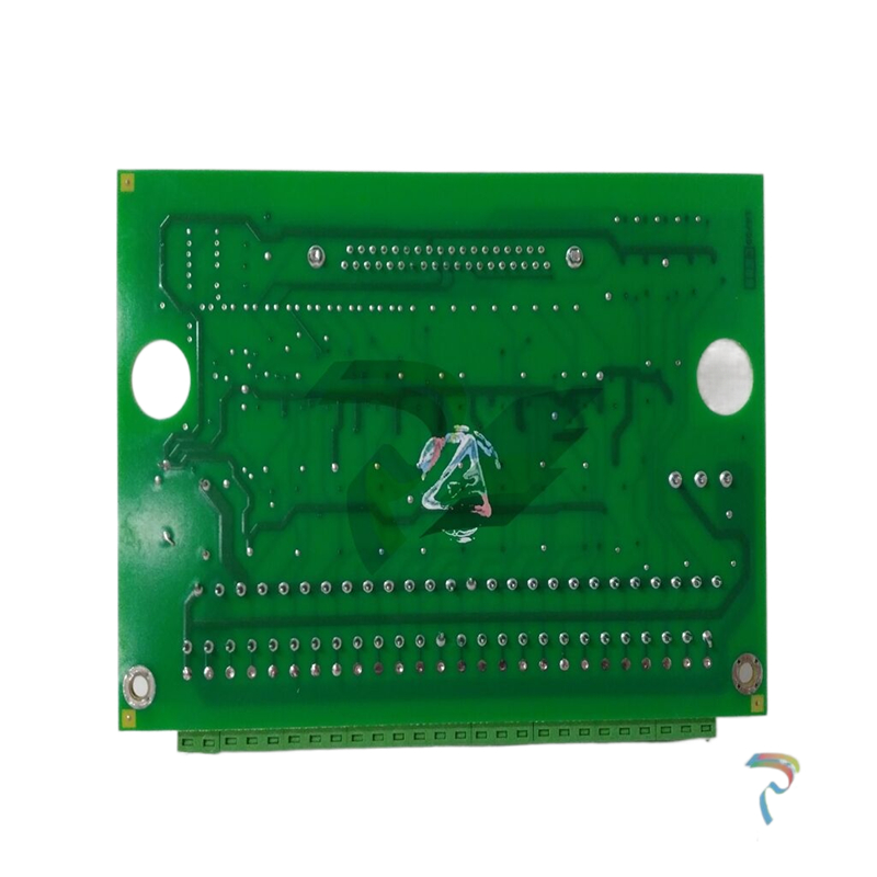
GE 8086-FC-20 20 + 24 pin cables for 8619 (2m)
An 8410-NS-PS Node Services Power Supply Monitor Module must be
installed on the Controller Carrier to make use of this capability. If an8410-NS-PS is not being used, then it is not necessary to make anyconnections to the PSU Power Fail terminalsTerminal pairs 1, 2, 4 and 5These terminal pairs are used to monitor the AUX (or power fail)output from up to four 8914-PS-AC power supplies.The upper terminal of each pair is connected directly to the AUXterminal of the 8914-PS-AC that is to be monitored. It is notnecessary to connect the lower terminal – as this is internallyconnected to the BFP0V terminal on the Carrier.If any of the 8914-PS-AC supplies are acting as redundant pairs,then these should be connected to terminal pairs 1 and 2 and/ orterminal pairs 4 and 5.If a pair is unused, a shorting link must be placed between the upperand lower terminals, otherwise the Power Supply Monitor Module willcontinuously report a fault.Terminal pair 3The upper terminal of this pair should be connected to the 24V dcsupply of the 8914-PS-AC supply monitored by terminal pairs 1 and2. The lower should be connected to the 24Vdc supply of the 8914-PS-AC monitored by terminal pairs 4 and 5.If a single pair of 8914-PS-AC power supplies is being monitored,then it is only necessary to make single connection to appropriateterminal of pair 3.Terminal pair 6
This terminal pair is unconnected and should not be used.
Terminal pairs 7 and 8
These terminal pairs are used to monitor the AUX (or power fail)output from up to two 8913-PS-AC power supplies.The upper terminal of each pair is connected directly to the AUXterminal of the 8913-PS-AC that is to be monitored. It is not necessaryto connect the lower terminal – as this is internally connected to theGND terminal on the Carrier.If a pair is unused, a shorting link must be placed between the upperand lower terminals, otherwise the Power Supply Monitor Module willcontinuously report a fault.Terminal pair 9If a Railbus Isolator (8922-RB-IS) is not used in the node, this terminalpair must be fitted with a shorting link to prevent an alarm conditionbeing signalled to the Controller.If a Railbus Isolator is used, internal connections are made to monitorthe failure of any power supplies used to provide power for theIntrinsically Safe IO Modules.ELECTRICAL CONNECTIONSRailbus connectors ……………………………….female in, male outCable screens/shield connections…M4 screw terminals (x34)Bussed field power supply connectors………8-pin male (x2)The two 8-pin connectors provided at the top rear of the carrierconnect power supplies for ‘field power’. These supplies are routedthrough I/O modules that require power for their field circuits.MECHANICALDimensions ……………………………342 (w) x 170 (d) x 22 (h)mmWeight ……………………………………………………………………680gMounting methods…………………………….Flat panel or DIN railDIN-rail types……….‘Top hat’ 35 x 7.5mm rail or 35 x 15mm rail to EN 50022………………………………………………..G-section rail to EN 50035Note: For applications with up to 4 IO Modules, it is possible touse the 4-module Carrier (8710-CA-04). For further information,contact MTL.


Leave a comment
Your email address will not be published. Required fields are marked *