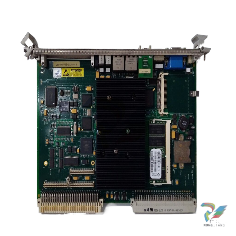
GE 8044-CC-20 Carrier extension cable, 2.0m
GE 8044-CC-20 Carrier extension cable, 2.0m
On-line download
Users with safety responsibility can
download new parameters to a SafetyNet
Controller, from a Trusted Host, to a
Controller whose Key Switch is set to permit
new downloads and where the particular
SafetyNet Controller’s Password is known.
New parameter download is carried out as a
background task over a number of cycles to
ensure that the fault reaction and response
times are not compromised. Once download
is complete and the new parameters have
passed the checking and security tests, the
new parameters will be automatically
adopted. Where redundant SafetyNet
Controllers are used, the stand-by Controller
will also be automatically updated.
Note: on-line download should only be used
where there are adequate procedures for
approving the changes that have been made
and testing them prior to download.
Static Analysis Tool
Any safety-related application program must
be developed by suitably qualified personnel
and must be subject to careful scrutiny to
ensure safety, but the Workbench provides
an additional safety test. The Static Analysis
Tool checks for illegal constructs within the
safety program prior to download.
Differences Utility
Once a new SafetyNet application is
successfully compiled, it can be downloaded
to a SafetyNet Controller. On download, two
text reports are generated: a Download
Report and a Master Tag Xref. These can be
used for comparison with other downloads
using the Differences Utility.
Download backup
A time stamped backup of each safety
application is automatically created
following a successful download. Changes
between versions can be viewed and
backups can be used either as a start point
for developing new safety applications or to
restore an earlier version.
Change Control Log
The Workbench maintains a Change Control
Log that records – for example – when:
♦ IO Modules are added, deleted or moved
♦ Tags are added to, removed from, or
moved within an IO Module
♦ IO Configuration parameters are saved
♦ Controller IP addresses or node
numbers are entered or modified
♦ External node numbers are entered or
modified
♦ Serial communications parameters are
entered or modified
♦ A successful download is made
♦ A Strategy is removed
♦ The Controller password is changed
General
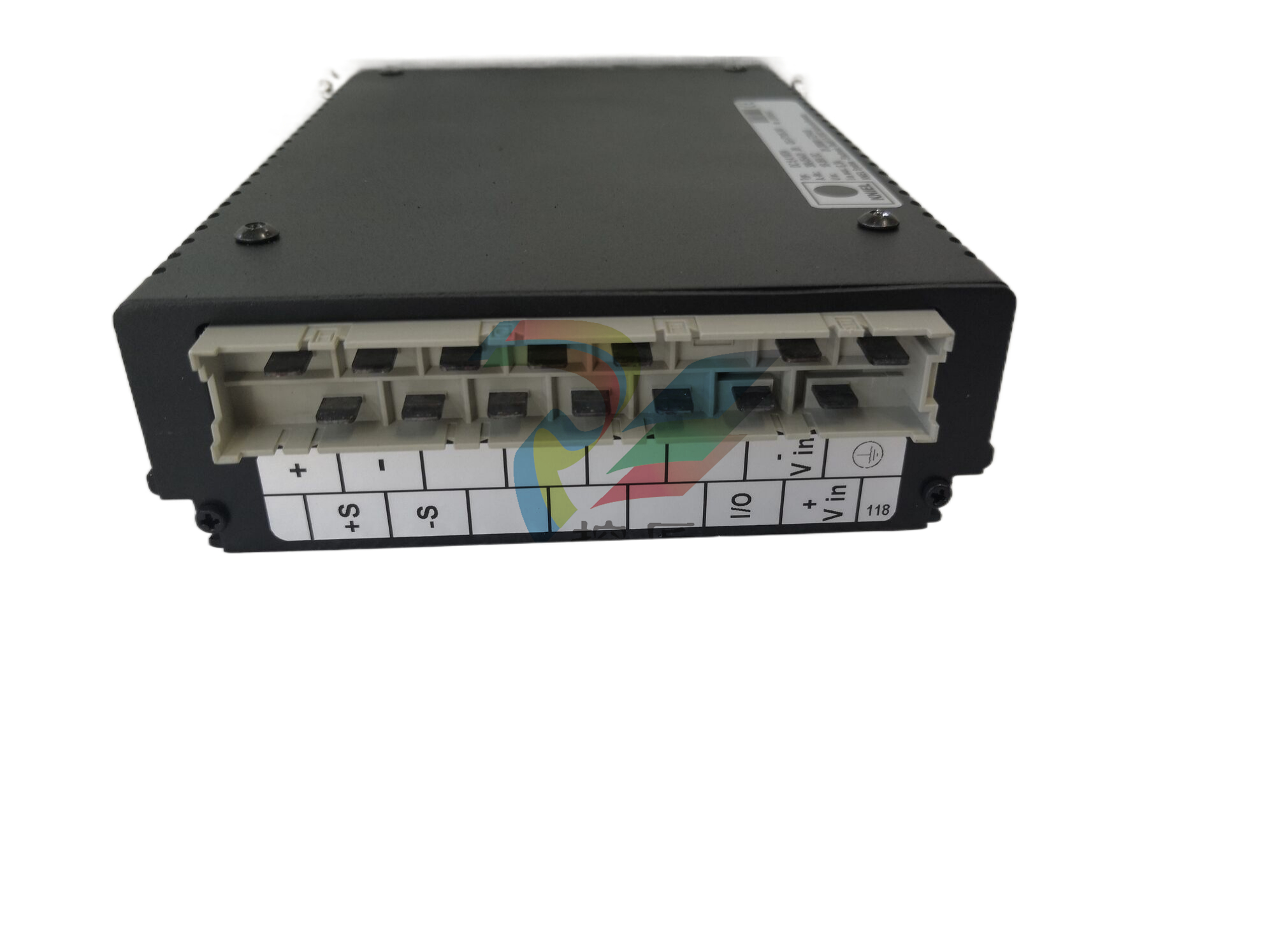
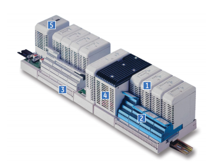
SafetyNet IO Modules interface to safety
system field wiring via Field Terminals.
The IO Modules and the Field Terminals
mount on Carriers that provide
mechanical support, but also connect the
internal communication bus and power
supply connections to the Modules.
The IO Modules are certified as suitable
for use in SIL 2 safety-related
applications.
Certification
The SafetyNet IO Modules are certified for
use in safety-related applications up to and
including SIL 2. The SafetyNet System
achieves this certification with a 1oo1D
architecture.
The SafetyNet IO Modules have been
designed specifically for safety-related
applications and are certified on the basis of
the excellence of their design. The
certification does not depend on “proven in
use” data.
Diagnostics
The IO Modules perform comprehensive
internal diagnostic tests as an essential part
of ensuring that the IO can carry out the
required safety function.
If the SafetyNet IO Module’s internal
diagnostics detect a fault that would prevent
the SafetyNet System from carrying out its
safety function, then it will initiate a controlled
shutdown. A controlled shutdown has two
objectives – firstly, to ensure that the IO
Module enters its failsafe mode; and
secondly, to record sufficient data to allow the
reason for the shutdown to be determined.
If a SafetyNet Module enters a controlled
shutdown, then all IO channels are de activated: input channels are not scanned;
and output channels are de-energised.
Bussed Field Power
The Bussed Field Power (BFP) connectors on
the rear of IO Module Carriers provide the
power connections for field instruments
wired to the IO Modules.
For the SafetyNet System, BFP must be 24V
dc and supplied by MTL’s 8914-PS-AC units.
These power supplies may be used in
redundant pairs, if required.
Live maintenance
SafetyNet IO Modules can be removed and
replaced in a Class 1, Division 2 or Zone 2
hazardous area – once the relevant Bussed
Field Power (BFP) connection has been
isolated using an appropriate hazardous
area switch (such as the MTL951). Removing
and replacing the Modules does not
interrupt the operation of the other parts of
the node.
If a Module is replaced by another Module
of identically the same type, then no
intervention is required for the System to
begin operating normally once the Bussed
Field Power is restored.